Mohr’s circle is a graphical representation of the state of stress at a point: the abscissa σ and the ordinate τ of a point of the diagram are the normal and shear stress acting on a plane through that point. In the general three-dimensional case, the Mohr diagram consists of three circles, as shown in Fig. 1. The Mohr diagram is often used together with failure criteria such as the Mohr–Coulomb failure criterion.
Figure 1: In three dimensions there are three Mohr’s circles, whose centers and diameters are calculated from the three principal stresses. The point P that represents the normal and shear stress on a plane does not necessarily lie on a circle; it is found from the direction cosines of the plane with the arcs AA′, BB′ and ΓΓ′.
Assume that the stress state at a point is given by the stress tensor:
σij=σ11σ21σ31σ12σ22σ32σ13σ23σ33(1)
The circles are drawn from the principal stresses σ1≥σ2≥σ3, which are calculated from the stress tensor as shown in Principal stresses and stress invariants. The circles cannot be drawn directly from the components of the tensor: a circle drawn with σ11, σ22 and σ12, as in the two-dimensional case, ignores the shear stresses σ13 and σ23 and is one of Mohr’s circles only if x3 is a principal direction. The centers of the circles lie on the σ axis and are given by:
Thus, the circle with center C1 passes through σ1 and σ2, the circle with center C2 through σ1 and σ3, and the circle with center C3 through σ2 and σ3.
As in the article on Mohr’s circle, compressive stresses are taken as positive. In three dimensions, however, the shear stress on a plane is a vector in the plane whose direction is not fixed by a single in-plane axis, so τ is the magnitude of the shear stress, τ≥0, and only the upper half of the diagram represents stress states. The special sign rule of the two-dimensional Mohr’s circle does not apply here; the parts of the circles below the σ axis are used only for the construction.
Normal and shear stress on a plane
Consider an arbitrary plane through the point, and let n1, n2 and n3 be the direction cosines of its unit normal vector with respect to the principal directions of σ1, σ2 and σ3, respectively. The stress vector on the plane has components σ1n1, σ2n2 and σ3n3 along the principal directions (see also Calculation of normal and shear stress on a plane), so the normal and shear stress satisfy:
Each of Eqs. (5) is a circle: for a given n1 the point (σ,τ) lies on a circle with center C3, for a given n2 on a circle with center C2, and for a given n3 on a circle with center C1. Since ni2≥0 and σ1≥σ2≥σ3, Eqs. (5) also show where the admissible points lie: the first and the third equation give (σ−C3)2+τ2≥R32 and (σ−C1)2+τ2≥R12, and the second gives (σ−C2)2+τ2≤R22. Hence, the point (σ,τ) of any plane lies inside or on the large circle (between σ1 and σ3) and outside or on the two small circles (between σ1 and σ2, and between σ2 and σ3). The points on the circles themselves belong to planes that contain one of the principal directions (n1=0, n2=0 or n3=0).
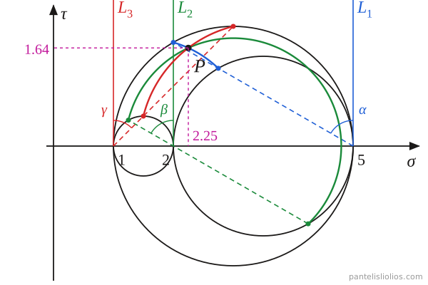
The circles of Eqs. (5) can be drawn without calculation (Fig. 1):
For n1: draw the line L1 through σ1, parallel to the τ axis. Draw a line through σ1 at the angle α=cos−1n1 from L1, towards the smaller stresses. It intersects the circle between σ1 and σ2 at A and the circle between σ1 and σ3 at A′. With center C3, the only center that does not depend on σ1, draw the arc AA′.
For n2: draw the line L2 through σ2 and a line through σ2 at the angle β=cos−1n2 from L2, towards σ3. It intersects the circle between σ2 and σ3 at B′; extended below the σ axis, it intersects the circle between σ1 and σ2 at B. With center C2, draw the arc BB′.
For n3: draw the line L3 through σ3 and a line through σ3 at the angle γ=cos−1n3 from L3, towards the larger stresses. It intersects the circle between σ2 and σ3 at Γ and the circle between σ1 and σ3 at Γ′. With center C1, draw the arc ΓΓ′.
The normal and shear stress on the plane are the coordinates of the intersection point P of the arcs. Since n12+n22+n32=1, only two of the direction cosines are independent, so two arcs are enough to find P. For example, we can use n1 and n3 to find P and n2 to check the construction, since all three arcs pass through P.
The Mohr diagram can thus be used to calculate the normal and shear stresses on a plane graphically. Alternatively, Eqs. (4) or the method described in Calculation of normal and shear stress on a plane may be used.
Example
Consider the following stress state at a point:
σij=500020001(6)
Calculate the normal and shear stress on the plane with normal vector:
n=(21,21,22)
Solution
The stress tensor (6) is diagonal, so the coordinate axes are the principal directions and σ1=5, σ2=2 and σ3=1. Hence, the components of n are the direction cosines n1, n2 and n3 with respect to the principal directions. From Eqs. (2) and (3) we calculate the centers C1, C2 and C3 and the radii R1, R2 and R3:
Next we draw the Mohr diagram, as shown in Fig. 2.
Figure 2: Calculation of the normal and shear stress on a plane with the three-dimensional Mohr diagram, for σ1=5, σ2=2, σ3=1 and n=(1/2,1/2,2/2).
From the direction cosines we calculate the angles α, β and γ:
α=cos−121=60∘β=cos−121=60∘γ=cos−122=45∘
Using these angles (only two are needed, for example α and γ) we draw the arcs, and their intersection point P gives the normal and shear stress on the plane: