Mohr's circle
In two-dimensional stress analysis, Mohr’s circle is a graphical representation of the stress state of a point in a body under static equilibrium. The two-dimensional loading state can be either plane stress or plane strain. For three-dimensional analysis we may use the extended Mohr’s circle for three dimensions (Mohr’s circle 3D).
Consider a body in equilibrium under two-dimensional loading (Fig. 1). The stress tensor for this case is:

In this article we use the sign convention of geomechanics: compressive stresses are positive. Consequently, positive stress components act in the negative coordinate directions on a face whose outward normal points in a positive coordinate direction, and in the positive coordinate directions on the opposite face (Fig. 1).
Consider now an arbitrary plane inside this body. The normal vector of this plane makes an angle with the horizontal axis . The stress vector that acts on this plane is (see also Calculation of normal and shear stress on a plane):
where are the direction cosines of the normal vector . The normal stress that acts on this plane is the projection of on :
Expanding Eq. (3) and taking into account that:
we derive the following expression:
The shear stress is the component of along the plane. Let be the unit vector along the plane, obtained by rotating by counterclockwise; is a local right-handed coordinate system attached to the plane. For the local system coincides with , so reduces to . The shear stress is the projection of on :
The Pythagorean theorem, , gives the same magnitude but loses the sign of ; the projection on keeps it. In accordance with the sign convention, a positive acts in the direction of and a positive in the direction of on the face whose outward normal is (Fig. 1). Substituting and from Eq. (2) into Eq. (6) leads to:
Eqs. (5) and (7) are the parametric equations of a circle. To show this, we rewrite Eq. (5) as follows:
Squaring Eqs. (7) and (8) and adding them, we obtain:
If we set
and
then Eq. (9) becomes:
which is the equation of a circle with center and radius in a coordinate system whose abscissa is the normal stress and whose ordinate is the shear stress (Fig. 2).
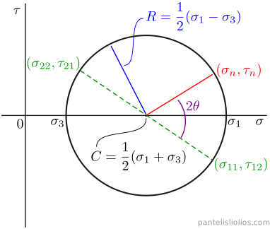
To construct Mohr’s circle for the stress tensor (1) we first define a special sign rule for the shear stress. Shear stresses that produce a counterclockwise moment about the center of the element (Fig. 1) are taken as positive and are plotted above the axis. Shear stresses that tend to rotate the element clockwise are taken as negative and are plotted below it. Because of moment equilibrium, the shear stresses on the vertical faces and on the horizontal faces of the element always rotate it in opposite senses, so the two points that represent these faces are always symmetric about the axis. For the stresses of Fig. 1, the shear stresses on the vertical faces rotate the element clockwise and those on the horizontal faces counterclockwise. Thus, we draw the points and as shown in Fig. 2. Next, we connect these two points with a straight line. This line is a diameter of the circle, and its intersection with the horizontal axis is the center of the circle. The distance between the center and either of the two points is the radius. Hence, we can now draw Mohr’s circle.
According to Eqs. (5) and (7), a plane at an angle (Fig. 1) corresponds to an angle on Mohr’s circle (Fig. 2). Hence, for a given plane it suffices to measure the angle on Mohr’s circle; the coordinates of the resulting point are the normal and shear stress that act on that plane. The angle is measured from the line connecting the center of the circle with , in the same sense as in the free body diagram (Fig. 2).
Next, we derive the principal stresses and their directions. If we set:
then from Eq. (7) we derive:
Eq. (14) has two solutions in the range :
The two angles and are called principal directions and give the directions of the two principal stresses. Substituting the angles from Eq. (14) into Eq. (5) and taking into account that:
leads to:
where and are the two principal stresses. To find which of the two angles belongs to , substitute into Eq. (5): if the result is , then is the direction of ; otherwise it is the direction of .
The same result follows directly from Mohr’s circle, without trigonometric identities. The principal stresses are the points of the circle with zero shear stress, i.e. the intersections of the circle with the axis (Fig. 2). Setting in Eq. (12) gives , so:
which, with Eqs. (10) and (11), is Eq. (17).
The maximum shear stress occurs where the derivative of the shear stress with respect to equals zero (Eq. (7)). The planes of maximum shear stress make an angle of with the principal directions, and the maximum shear stress is equal to the radius of Mohr’s circle:
Eq. (19) holds for planes parallel to the -axis, i.e. the planes considered in two-dimensional analysis. Planes inclined to the -axis may carry higher shear stresses. For example, in plane stress () with and of the same sign, the absolute maximum shear stress is half of the principal stress with the larger absolute value, on planes inclined at to the -axis. These planes are covered by Mohr’s circle in three dimensions.
Constructing Mohr’s circle step by step
- Plot the point of the vertical faces, , and the point of the horizontal faces, , with the sign of the shear stress given by the special rule (counterclockwise positive).
- Connect the two points. The line is a diameter of the circle and crosses the axis at the center , Eq. (10).
- Draw the circle with center through the two points. Its radius is , Eq. (11).
- The circle crosses the axis at the principal stresses and . Its highest and lowest points give .
- For a plane whose normal makes an angle with , rotate by from the point of the vertical faces, in the same sense as , or use a pole point (next section).
Pole points
So far we have discussed two methods to calculate the normal and shear stress on an arbitrary plane. The first is to use Eqs. (5) and (7), and the second is to measure the angle on Mohr’s circle. An alternative graphical method is to use a pole point on Mohr’s circle.
Two pole points can be established on Mohr’s circle. The first is related to the directions of the stresses and the second to the planes on which the stresses act. Consider the case of Fig. 1, for which we construct Mohr’s circle as in Fig. 2. The pole for stresses is found by drawing a horizontal line from point , parallel to the direction of , or a vertical line from point , parallel to the direction of (Fig. 3). Both lines intersect Mohr’s circle at the same point, the pole for stresses (). The pole for planes is found by drawing a vertical line from point , parallel to the plane on which acts. Similarly, we may draw a horizontal line from point , parallel to the plane on which acts. Both lines intersect Mohr’s circle at the same point, the pole for planes ().
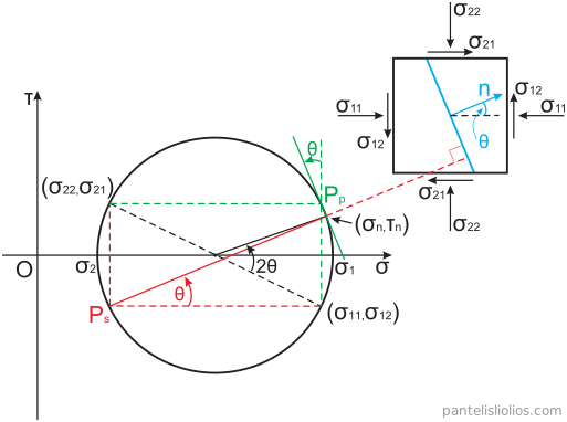
Consider now an arbitrary plane whose normal vector makes an angle with , as shown in Fig. 3. We can use either pole to calculate the normal and shear stresses that act on this plane. If we use the pole for stresses, we draw a straight line from the pole perpendicular to the plane (parallel to the normal vector ). The second intersection point between this line and Mohr’s circle gives the normal and shear stresses that act on the plane. Equivalently, we draw a straight line from at the angle , measured counterclockwise from the horizontal axis (Fig. 3). If we use the pole for planes, we draw a straight line from the pole parallel to the plane of interest. Its second intersection point with Mohr’s circle is the same point.
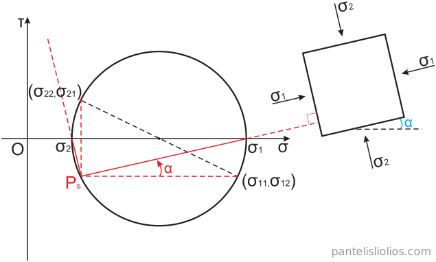
Both poles can also be used to find the directions of the principal stresses. Here we use the pole for stresses . From we draw straight lines to the two principal stresses and on Mohr’s circle (Fig. 4). The angle of the line to , measured counterclockwise from the horizontal axis, is the angle between the direction of and the direction of (the -axis).
Important note
The sign of the shear stress calculated by Eq. (7) refers to the local right-handed coordinate system attached to the plane: a positive acts in the direction of on the face whose outward normal is , just as a positive acts in the direction of . The sign of the shear stress on Mohr’s circle follows the special rule defined previously: shear stresses that tend to rotate the element counterclockwise are positive and negative otherwise. A shear stress in the direction of , on the face whose outward normal is , tends to rotate the element clockwise. Thus, a positive shear stress calculated by Eq. (7) is plotted as negative on Mohr’s circle and vice versa; this is why the point of the plane in Fig. 2 is .
Example
Consider a solid body under plane stress loading, as shown in Fig. 1. The stresses acting on this body are given by the following stress tensor:
Consider also an inclined plane inside this body, whose normal vector makes an angle of with the horizontal axis. Calculate the normal and shear stress on this plane by using Eqs. (5) and (7) and by using the pole on Mohr’s circle. Also, calculate the principal stresses, the principal directions and the maximum shear stress.
Solution
By using Eq. (5) we calculate the normal stress:
For the shear stress we use Eq. (7):
We use Eq. (17) to calculate the principal stresses:
The directions of the principal stresses are calculated by Eq. (14):
Substituting into Eq. (5) gives . Hence, is the direction of and is the direction of .
The maximum shear stress is equal to the radius of Mohr’s circle, Eq. (19):
and acts on the planes at , i.e. at and . Since this is plane stress () and both principal stresses are compressive, the absolute maximum shear stress, on planes inclined to the -axis, is (see Mohr’s circle 3D).
To construct Mohr’s circle we first draw the two points from the stress tensor (20). The shear stresses on the vertical sides of the element tend to rotate it clockwise, so according to the special rule they are negative and the point of the vertical faces is . The shear stresses on the horizontal sides tend to rotate it counterclockwise, which gives the point . Then we connect these two points and find the center of the circle, (Fig. 5). With this center and a radius equal to the distance between the center and either of the two points, , we draw the circle.
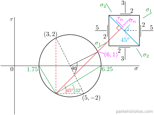
Next we draw a horizontal line from point , parallel to the direction of . Its second intersection point with the circle, , is the pole for stresses . The normal and shear stress on the plane of interest are found either by drawing a line at from the pole or by rotating by counterclockwise around the center from the point ; both give the point . The intersection points of the circle with the horizontal axis are the principal stresses and . We connect the pole with these points and measure the angles of the principal directions with respect to the -axis of the stress tensor (20): for . Note that the shear stress on Mohr’s circle is positive (), which means that it tends to rotate the element counterclockwise. The shear stress from Eq. (22) is negative, which means that it acts in the direction of on the face whose outward normal is (a positive would act in the direction of ). Both methods give the same direction for the shear stress. In Fig. 5 we have drawn on the plane the directions of and .
Mohr’s circle is also the basis of the Mohr–Coulomb failure criterion, which predicts failure from the position of the circle relative to a failure envelope.